
High-tech enterprise specializing in the research and development, production and sales of new geosynthetic materials such as geotextiles, geomembranes, geogrids, and geocells.
Email:shaun@zhongloo.com
geogrid retaining wall design example
- In order to reduce the differential settlement at the junction of excavation and filling, the foundation in contact with excavation and filling in the vertical and horizontal directions shall be treated, the roadbed (80cm) shall be excavated at the junction of excavation and filling, and earthwork grids shall be set on the top surface of the embankment and the ground, and the filling shall be completed. In addition to the treatment of the side embankment in strict accordance with the technical requirements in the “Subgrade Filling Design Drawing”, the pressure of the upper and lower embankments at the base will be increased by 1%, that is, after surface cleaning treatment, the foundation will be 91%, the lower embankment will be 94%, and the upper embankment will be 95%. %, the excavation at the interface shall not be less than 2 meters wide, and a 2% inward transverse slope shall be set, and the filling section at the junction of longitudinal filling and excavation shall be subjected to dynamic compaction. Carry out over-excavation and backfill compaction, and set up geogrids on the top and bottom of the over-excavation backfill. The two sides of the interface are not less than 5 meters, and the base of the filling part is treated with an 80 cm 8% lime soil cushion.
- Construction method and key points of fill-excavation handover treatment:
(1) Clear the topsoil: plant soil and turf on the surface of the filling and excavation section not less than 30cm
The soil, tree roots and soil containing decaying substances shall be removed and piled up in the spoil yard. (2) Measurement and stakeout: Restoring the center line of the line according to the approved traverse points and benchmark points, nailing out the middle and
side piles, and lead the side piles to the site red line piles for fixation, measure and calculate the vertical and horizontal lower embankment top, upper embankment top fill-excavation junction line (the center line of the lower layer and upper layer geogrid) with a level gauge, and spread the nail piles Line markers, sideline peripheral stakes fixed. (3) Excavation steps: half-fill and half-excavate before filling and rolling along the longitudinal direction of the route, the filling section intersects with the excavation section
Use bulldozers or excavators to excavate steps with a width of not less than 2m along the boundary, and set a 2%-4% inward slope for the steps.
(4) Rolling before filling: use a vibratory roller ≥ 18T for rolling, and when rolling, the interface
(Including steps) Press twice more, and the compactness test shall not be lower than 91%.
(5) Construction of 80cm thick 8% lime soil cushion: construction points are the same as those of high embankment 8% lime soil cushion
same. It’s just that the compaction test must not be lower than 94%. (6) Filling roadbed construction: Filling and construction method of filling roadbed construction and 3% ash mixed roadbed
Construction is the same. It’s just that the compaction test must not be lower than 94%. (7) Geogrid laying
① Bottom geogrid laying: After the subgrade is filled to the top of the lower embankment, when excavating and filling the steps of the excavated square section at the junction, the excavation width shall not be less than 7m, and the rolling compaction of the step surface shall not be less than 91%. , Manually clean up the laying surface of the geogrid. The geogrid is laid with the intersection line marked by the nail pile as the axis, and the vertical and horizontal sections are laid. And care should be taken to avoid excessive stretching so as to avoid damage or tearing, partial bursting, etc. due to exceeding the limit of its strength and deformation.
② Laying of the upper geogrid: the laying position of the upper geogrid is the top surface of the road. After the subgrade is filled with 3% lime soil to the top of the embankment, it is level with the bottom level of the road bed treatment, and the grid paving surface is manually arranged, and the laying method is the same as that of the bottom grid. ③ Middle layer geogrid laying: the middle layer geogrid laying position is the top surface of the upper embankment, after the 3% lime soil fill subgrade is filled to the top of the upper embankment, the rolling geogrid laying surface is arranged, and the paving width is deep excavation Section 5m, the geogrid laying method is the same as the bottom laying
(8) Quality control points for geogrid laying
① The geogrid at the intersection of longitudinal filling and excavation of the subgrade is laid horizontally along the subgrade, and the laying length is along the direction of the subgrade cross section to 30cm outside the fill slope.
Cut off the exposed part at all times. The geogrid at the junction of horizontal filling and excavation of the subgrade is laid along the longitudinal direction of the subgrade, and the laying length is 30 cm beyond the section of the half-filled and half-dug subgrade. ② The performance parameters of the geogrid meet the corresponding requirements of the national standard.
③ The width of the overlap between the two geogrids is 33cm, and the overlap is made of polyethylene rope in a “zigzag” shape. U-shaped nails are used to tighten the soil of the geogrid with a spacing of 1.5m*1.5m
④ When continuing to fill the subgrade on the completed geogrid, when pushing the mixed filler, the shovel should be raised and pushed to cover all the geogrid, and then spread according to the loose paving thickness, supplemented by manual inspection Clear hard fast materials to prevent distortion and displacement of geogrid.
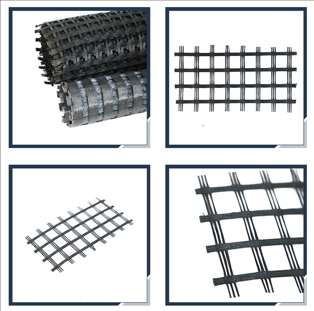
Geogrid Construction Technology
Geogrid construction process: detection and cleaning of the underlying layer—manual laying of geogrid—lapping, binding, fixing—spreading of upper subgrade soil—rolling—inspection. The geogrid is laid on the flat lower bearing layer according to the width required by the design, and the upper and lower layers of the filler do not have sundries that can damage the geogrid. When laying the geogrid, the direction of high strength should be arranged perpendicular to the axis of the embankment. The geogrid is laid horizontally. Tighten and straighten when laying to avoid wrinkles, twists or potholes. The geogrid is spliced longitudinally using the lap joint method, and the lap joint width is not less than 30cm. After the geogrid is laid, the upper layer of filler is manually laid, and the rolling is completed in time to avoid long-term explosion. Then use mechanical transportation, leveling and rolling. Mechanical paving and rolling are advanced from both sides to the middle, and the compaction degree is maintained to meet the specification requirements.
Put an end to all construction vehicles and construction machinery driving or parking on the laid geogrid, check the quality of the geogrid at any time during construction, and repair and replace according to the degree if any damage such as breakage, puncture, tearing, etc. is found.
Geogrid construction specification
The construction direction of the geogrid is always perpendicular to the center line of the subgrade. 1. Preparatory work for laying:
1.1 Foundation treatment: Firstly, level and roll the lower layer. The flatness is required to be no more than 15mm, and the degree of compaction meets the design requirements. Hard raised objects such as crushed stones and boulders are strictly prohibited on the surface. 1.2 Laying environment: the outdoor temperature is above 5°C, the wind force is below level 4, and there is no rain or snow. 2. Laying and lapping method:
2.1 Lay the geogrid on the flat lower bearing layer according to the designed width. When paving, it should be straightened and smooth, and it should be close to the lower bearing layer. There should be no distortion, folds or overlaps. U-shaped nails or connectors should be used for the lap joints. fixed.
2.2 When laying the geogrid, the direction of the main strength of the reinforcement is perpendicular to the axis of the embankment, and the superimposed length (longitudinal) of each piece is not less than 15cm, and is fixed with U-shaped nails or connectors, with a spacing of 1.0m and a horizontal lap length of 30 -90cm, the overlapping position is fixed with U-shaped nails or nylon rope. 3. Quality inspection after lapping:
3.1 After the geogrid is laid, first conduct self-inspection, and its quality requirements are shown in the following table: No. Item construction quality inspection methods and requirements 1 Underlayer flatness 15cm degree 2 Longitudinal lap width 15cm degree 3 Horizontal lap width ≥ 30cm Spot check 2% Frequency Check 4 spot checks every 200m 2%